top of page
How to Assemble your Asher Rod Locker
The following is a step by step procedure to assemble and mount your new Rod Locker.

Step 1
Complete kit with all the hardware as shipped to you.

Step 2
Slide front and rear sections together. Starting with the lower body, then connecting the lid as the gap closes.

Step 3
Start all the supplied screws with flat washers. After 13 screws have been started, tighten the bottom 6 first. Then move around the box until all the screws are tight. The screws have Teflon infused tips keeping them from vibrating out during driving. They do not need to be over tightened to maintain strength.

Step 4
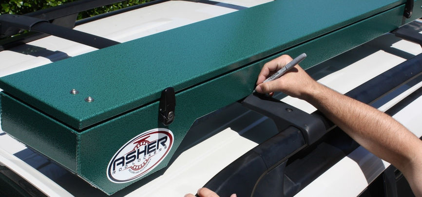
With the tailgate fully extended open, set the rod locker on your cross beams. In many cases sliding the locker back within a few inches of the tail gate will be the optimal position.
Step 5
Put a mark just above the center of front and rear cross bar Then remove the locker from your vehicle for marking and drilling.

Step 6
Put a mark just above the center of front and rear cross bar Then remove the locker from your vehicle for marking and drilling.
Step 7
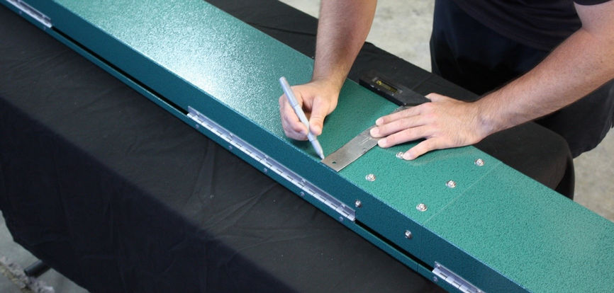
With the use of a marker and a square, mark a line across the bottom of the box at the same mark showing the center of the cross beams.

Step 8
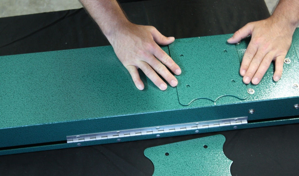
Lay the support plate on the bottom of the box aligning the points of the plate with the marked line. Keep the gap even on both sides of the plate to the edge of the box.
Step 9
Holding the plate in place mark the inside of all 4 holes of each plate.
Step 10
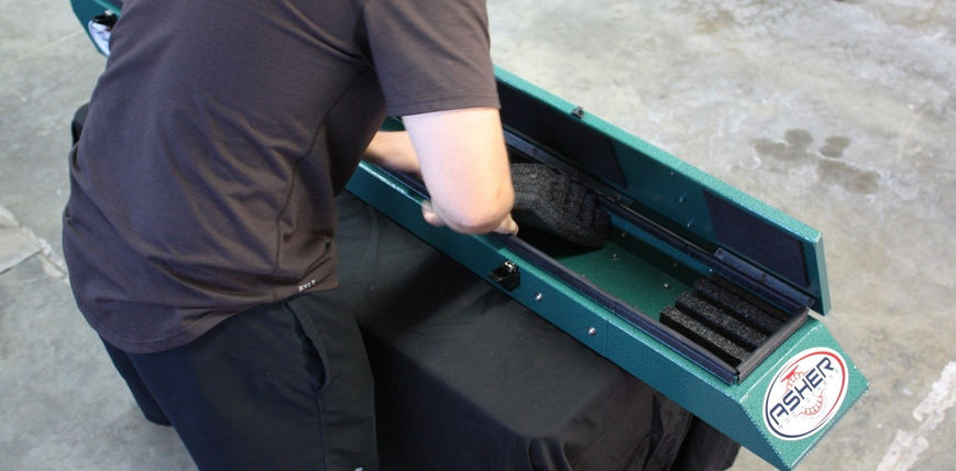
Open the locker and remove any foam sections that are in the path of the drill. This is done by rolling the edge of form inward on one side. Also ensure that there are no issues that would inhibit the mounting bolts. This is possible if the mounting hardware is in the same area where the front and rear section of the rod locker merges. If this is the case, adjust the position of the cross bars or adjust the box forward or back for a better location. Then repeat marking steps.

Step 11
Using a hammer and punch put a small indentation in the center of the hole mark for drilling.

Step 12
Drill a 1/8” pilot hole in all 8 marks. Then increase the drill bit size to ¼” and re-drill all 8 holes.

Step 13
Increase to a final hole size of 3/8”. This will match the hole size of the support plate that was used as a template.
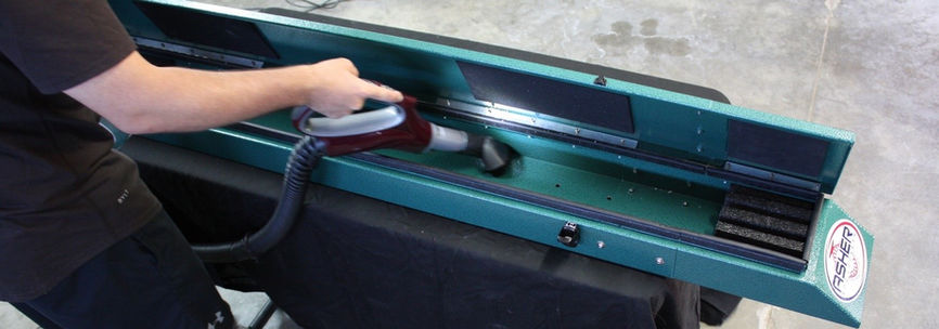
Step 14
Open your box and vacuum out all the aluminum shavings.

Step 16
Place the support plates underneath the locker between the locker and the crass bars. The support plate is necessary for the transfer of pressure across the bottom of the locker. Align the holes of the support plates with the holes drilled in the locker.Place the support plates underneath the locker between the locker and the crass bars. The support plate is necessary for the transfer of pressure across the bottom of the locker. Align the holes of the support plates with the holes drilled in the locker.


Explore Our Shop
bottom of page
